Week 10: Output Devices
DHT22 Sensor → SSD1306 OLED Display + NeoPixel Humidity Indicator
I²C 1-WIRE 3.3 V / 5 V WS2812B
Overview
In this week's group assignment, we measured the current consumption of an LED strip under different settings. We tested two inexpensive USB current meters, which gave slightly different readings. Both provided enough precision to ensure the power supply current limits are not exceeded. We also installed the necessary libraries to run a servo motor and an OLED display with the microcontroller For This week I am building a real-time environmental monitor driven by a DHT22 temperature and humidity sensor. The sensor feeds two independent output peripherals simultaneously:
- A 128×64 SSD1306 OLED display — renders temperature and humidity as live text over I²C.
- A 3-LED WS2812B NeoPixel strip — colour-codes the current humidity band in real time.
Components
🌡 DHT22 (AM2302)
Capacitive humidity + NTC temperature sensor. Single-wire proprietary protocol. Range: 0–100 % RH, −40–80 °C. Accuracy: ±2 % RH, ±0.5 °C. Minimum 2 s between readings.
📺 SSD1306 OLED 0.96″
128×64 pixel monochrome OLED. I²C interface at address 0x3C (some modules use 0x3D). Operates at 3.3 V or 5 V. Self-emissive — no backlight, excellent contrast in dim environments.
💡 WS2812B NeoPixel ×3
Addressable RGB LEDs daisy-chained on a single data line. 5 V, up to 60 mA per LED at full white. Controlled via Adafruit NeoPixel library. No extra clock wire needed.
🖥 Microcontroller
Xiao esp32-c3. I will be using the PCB I made in week 8.
🔋 Power Budget
OLED ≈ 20 mA. NeoPixels at 80/255 brightness ≈ 80 mA total. DHT22 ≈ 1.5 mA. Total ≈ 102 mA — USB power from the development board is sufficient.
Wiring & Pinout
All components connect directly to the custom PCB header pins. No breadboard or additional passives — wiring goes straight from header to component.
DHT22 → PCB Header
| DHT22 Pin | PCB Header Pin | Signal |
|---|---|---|
| 1 — VCC | [ VCC pin ] | Power |
| 2 — DATA | [ D9 ] | Digital signal |
| 3 — GND | [ GND pin ] | Ground |
SSD1306 OLED → PCB Header (I²C)
| OLED Pin | PCB Header Pin | Signal |
|---|---|---|
| VCC | [ VCC pin ] | Power |
| GND | [ GND pin ] | Ground |
| SDA | [ D4 ] | I²C Data |
| SCL | [ D5 ] | I²C Clock |
NeoPixel Strip → PCB Header
| NeoPixel Pin | PCB Header Pin | Signal |
|---|---|---|
| +5 V | [ VCC pin ] | Power |
| GND | [ GND pin ] | Ground |
| DIN | [ D6 ] | LED data signal |
This is what it looks like when connected:
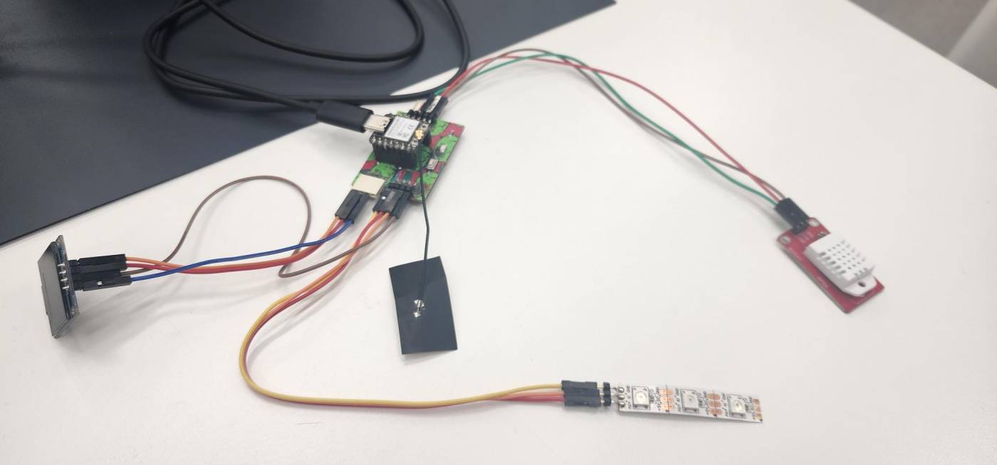 +
+
Program Logic
The firmware loop runs every 2 seconds — the minimum safe polling interval for the DHT22.
NeoPixel Humidity Colour Mapping
All three LEDs display the same colour simultaneously to form a clear visual band. Brightness is set to 80/255 (~31%) to be eye-safe and keep current draw within USB limits.
Code
The code was written by me for arduino IDE. The functionality essentially is it reads the temperature and humidity values from the DHT22 sensor and then updates the OLED display and NeoPixel strip accordingly.
See Section 06 for library installation.
#include <DHT.h>
#include <Wire.h>
#include <Adafruit_GFX.h>
#include <Adafruit_SSD1306.h>
#include <Adafruit_NeoPixel.h>

// ── Pin definitions ────────────────────────────────────────
#define DHT_PIN       D9      // DHT22 DATA pin
#define DHT_TYPE      DHT22
#define NEO_PIN       D6      // NeoPixel DIN pin
#define NEO_COUNT     3      // Number of LEDs
#define SCREEN_WIDTH  128
#define SCREEN_HEIGHT 64
#define OLED_RESET    -1     // -1 = share Arduino reset pin
#define OLED_ADDR     0x3C   // Try 0x3D if display is blank

// ── Object instances ───────────────────────────────────────
DHT               dht(DHT_PIN, DHT_TYPE);
Adafruit_SSD1306  display(SCREEN_WIDTH, SCREEN_HEIGHT, &Wire, OLED_RESET);
Adafruit_NeoPixel strip(NEO_COUNT, NEO_PIN, NEO_GRB + NEO_KHZ800);

// ── Humidity → RGB colour ──────────────────────────────────
uint32_t humidityColour(float humidity) {
  if (humidity < 30) return strip.Color(0,   0,   200); // Blue   — very dry
  if (humidity < 60) return strip.Color(0,   200, 0);   // Green  — comfortable
  if (humidity < 80) return strip.Color(200, 150, 0);   // Yellow — humid
  return               strip.Color(200, 0,   0);        // Red    — very humid
}

void setup() {
  Serial.begin(115200);
  dht.begin();

  // NeoPixel initialisation
  strip.begin();
  strip.setBrightness(80);
  strip.show();

  // OLED initialisation
  if (!display.begin(SSD1306_SWITCHCAPVCC, OLED_ADDR)) {
    Serial.println("SSD1306 not found — check wiring!");
    while (1);
  }
  display.clearDisplay();
  display.setTextSize(1);
  display.setTextColor(SSD1306_WHITE);
  display.setCursor(0, 0);
  display.println("Initialising...");
  display.display();
  delay(1000);
}

void loop() {
  float temp = dht.readTemperature(); // Celsius
  float hum  = dht.readHumidity();

  // Validate — DHT22 returns NaN on read failure
  if (isnan(temp) || isnan(hum)) {
    Serial.println("DHT22 read failed — check wiring!");
    delay(2000);
    return;
  }

  // ── OLED update ───────────────────────────────────────────
  display.clearDisplay();
  display.setTextSize(2);
  display.setCursor(0, 0);
  display.print("T: ");
  display.print(temp, 1);
  display.println(" C");
  display.setCursor(0, 28);
  display.print("H: ");
  display.print(hum, 1);
  display.println(" %");
  display.setTextSize(1);
  display.setCursor(0, 56);
  display.print("Output Devices — Week 10");
  display.display(); // push framebuffer to screen

  // ── NeoPixel update ───────────────────────────────────────
  uint32_t col = humidityColour(hum);
  for (int i = 0; i < NEO_COUNT; i++) {
    strip.setPixelColor(i, col);
  }
  strip.show();

  // ── Serial debug ──────────────────────────────────────────
  Serial.printf("Temp: %.1f C  Hum: %.1f%%\n", temp, hum);

  delay(2000); // DHT22 minimum safe polling interval
}
Libraries
Install all five via Sketch → Include Library → Manage Libraries in the Arduino IDE. The libaries all have examples to test the components so I referred to them how to set oled screen up.
| Library | Author | Purpose |
|---|---|---|
| DHT sensor library | Adafruit | Read temperature & humidity from DHT22 |
| Adafruit Unified Sensor | Adafruit | Required dependency for the DHT library |
| Adafruit SSD1306 | Adafruit | Drive the SSD1306 OLED over I²C |
| Adafruit GFX Library | Adafruit | Graphics primitives — text, shapes, bitmaps |
| Adafruit NeoPixel | Adafruit | Control WS2812B addressable LEDs |
💡 TIP: When you install DHT sensor library, the IDE will prompt you to also install Adafruit Unified Sensor — click "Install All" to grab both at once.
Process & Photos
Here is a photo of what it looked like when everything was connected with the code flashed:
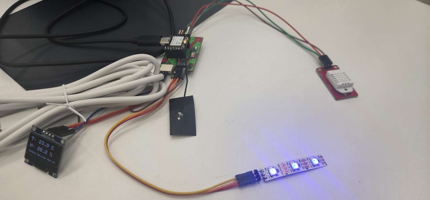
The OLED displays the current temperature and humidity readings, while the NeoPixel strip changes colour based on the humidity level. In this photo, the humidity is around 30%, so the LEDs are blue indicating dry conditions.
And here is a short video of the display and NeoPixels updating in real time as I had breathed on the DHT22 sensor just before taking the video to change the humidity:
As can be seen the neopixel change from yellow to blue as the humidity decreases and the oled updates accordingly.
Additional Work
I wanted an animation to run between the intializing and the display of the values. So I went to Tenor to find a suitable animation. I found one and downloaded it in gif form. Next was to convert it into singular frames and then change the frames into hex values.
For that I found a good tutorial that I followed for the next step.
First I needed to resize the gif for which I went to EZGIF. Since the oled screen is 128 x 64 pixels I resized it to fit the screen.
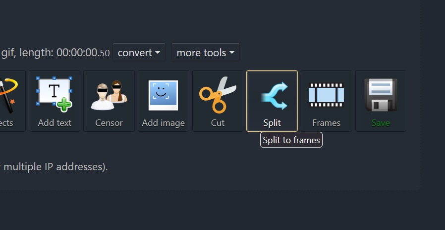
Next I needed to convert the gif into singular frames. For that I used the split function on the same website.
This ended up giving me 10 individual frames which I downloaded as a zip file.
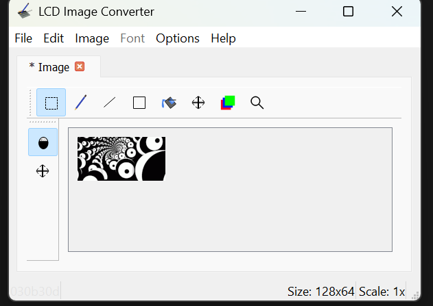
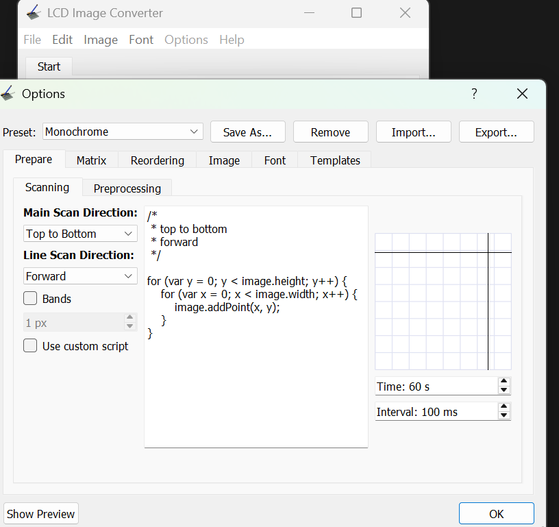
The tutorial then linked a software called LCD image converter to convert the frames into hex values.
I downloaded the software and then uploaded each image one by one and then at the end converted them all which gave 10 different c files.
Next was to get the hex values for each frame into one file instead of 10 different files.
Once I had converted all the frames, I realized an issue. I didn't change the preset from colour to monochrome which gave 24,576 bytes which is too much for the oled screen. So I had to reconvert them with the correct preset which was monochrome for which I went to options>>conversion and selected monochrome.
Now I had 10 C files again and then I opened an arduino sketch to combine all of them. This was tedious work. The file was then named "animation.h" so I can call the file in the main one.
Now this was done the main code had to be slightly changed so it could display the animation. I asked Gemeni for help. I gave the following prompt:"I now have an arudino file with 10 frames of animationa and now I wanna link it to the main file where I am already getting getting input from a dht sensor and then displaying it on an OLED screen and using neopixel strip to show humidity. I just want to run the animation in the start for few seconds before the main code starts." I also gave it the main code.
The main additions to the code by Gemini were:
// ── Animation Logic ────────────────────────────────────────
void runIntroAnimation(int repetitions) {
  for (int r = 0; r < repetitions; r++) {
    for (int i = 0; i < totalFrames; i++) {
      display.clearDisplay();
      display.drawBitmap(0, 0, all_frames[i], 128, 64, SSD1306_WHITE);
      display.display();
      delay(80);
    }
  }
}

void setup() {
  // ... initial hardware setup ...

  // Play intro before starting sensor loop
  runIntroAnimation(5);

  // Give DHT sensor time to warm up
  display.clearDisplay();
  display.setCursor(20, 28);
  display.println("Syncing Sensor...");
  display.display();

  dht.begin();
  delay(2000);
}
So it added a function called `runIntroAnimation` and then added a delay after the animation to allow the sensor to warm up as the dht sensor is slow.
Now when the code is run, the animation plays for a few seconds before the main loop starts and the sensor readings are displayed on the OLED and NeoPixels.
Here is a video of the animation playing on the OLED screen:
Overall this was a fun addition to the project and it was interesting to see how I could add an animation to the start of the code.
Download Files
 ← Back to Main Page